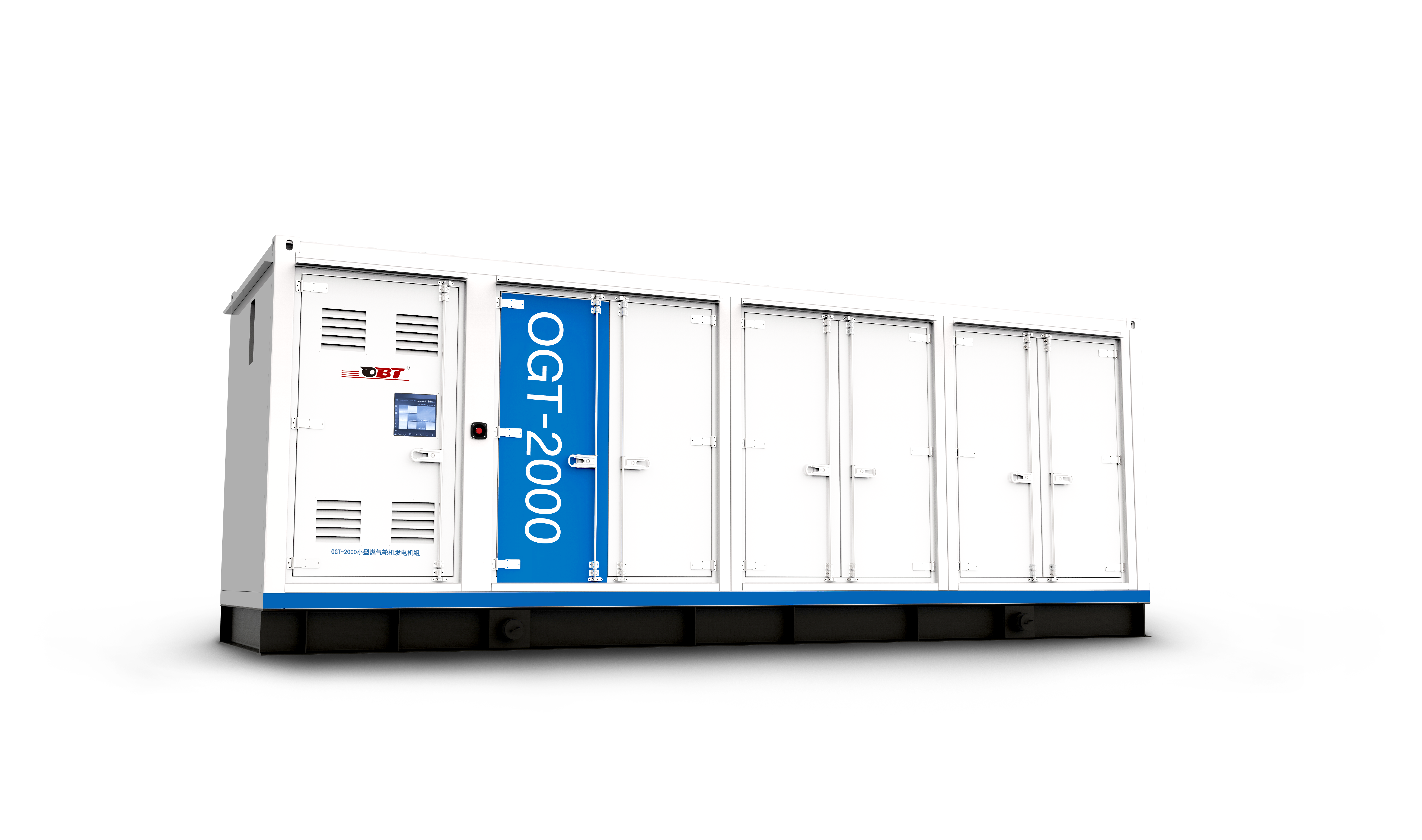
Plynová turbína OBT
OGT- 2000 Malé Plyn Turbi ne
Parametre |
Jednoduchý Cyklus |
Regeneračný Cyklus |
|
|
Elektrické výkon[1] |
Menovitý výstupný výkon kW |
1966 |
1721 |
Menovité výrobné výkony účinnosť % |
20.7 |
30.4 |
|
|
Požiadavky na palivo |
Typ paliva |
Prírodná plyn |
Prírodná plyn |
Palivo výhrevnosť hodnota bežná gE MJ/Nm³ |
30~37 |
30~37 |
|
Palivo zásobná tlak bar(g)[9] |
6~8 |
6~8 |
|
Prietok paliva pri menovitom výkone podmienkach Nm³/h[2] |
1005 |
599 |
|
Tepelná účinnosť kJ/kWh |
17391 |
11842 |
|
|
Chvost plyn |
Emisie NOx v ppmv |
≤25 (pri 15 % kyslíka obsah h) |
≤25 pri 15 % kyslíka obsah) |
Komín plyn priestorový tok kg/s |
11.9 |
11.6 |
|
Priestupný prietok spaľovacích plynov v m³/h (prevádzkový stav) |
104209 |
70628 |
|
Priestupný prietok spaľovacích plynov v Nm³/h (štandardný stav)[10] |
33439 |
32521 |
|
Komín plyn teplota ℃ |
578 |
320 |
|
|
Rozmery a hmotnosť |
D׊×Vmm |
8000×2420×3331 Celková výška kompletnej e jednotky, vrátane systému na úpravu vzduchu: vstup 6652 |
8000×2420×3331 (Regenerátor: 3786 × 5979,5 × 2800) |
Hmotnosť T |
30 |
40 |
|
Environmentálny výkon (pri |
Hluk vzdialenosti) 1m d B(A) |
≤85 |
≤85 |
|
KOG |
Par výstup t/h[3] |
7.7 |
2.7 |
Sušenie teplo kW[4] |
6006 |
2449 |
|
Horká voda výstup t/h [5] |
120.6 |
54.9 |
|
|
KOKOG
|
Chladenie výkon: kW[6] |
8262 |
1969 |
Chladivý výkon: 10 000 kcal/h [6] |
711 |
169 |
|
Kúrenie výkon: kW [7] |
5296 |
1999 |
|
Vykurovací výkon: 10 000 kcal/h [7] |
455 |
172 |
|
Energia dodávka plocha: m²[8] |
91800~206600 |
21900~49200 |
|
Poznámky: [1] Menovitý prevádzkový výkon za štandardných podmienok (15 °C, 101,325 kPa, relatívna vlhkosť 60 %).
[2] Vypočítané na základe nižšej výhrevnosti zemného plynu 34 MJ/Nm³ (štandardné podmienky pre Nm³: 0 °C a 101,325 kPa).
[3] Výstup pary je založený na tlaku pary 0,8 MPa(g) a teplote pary 175 °C.
[4] Sušiaci tepelný výkon je založený na teple spalín pri teplotách vyšších ako 120 °C.
[5] Výstup horúcej vody je vypočítaný za podmienok vstupnej teploty vody 15 °C, výstupnej teploty vody 60 °C a teploty výstupných spalín 75 °C. [6] Chladiaci výkon je získaný pri teplote výfukových plynov absorpčného chladiča 160 °C, pri jednoduchom cykle s COP = 1,5 a pri cykle s využitím odpadového tepla s COP = 1,0.
[7] Vykurovací výkon je vypočítaný na základe teploty výfukových plynov absorpčného chladiča 145 °C a COP = 0,93.
[8]Oblasť dodávky energie sa vypočíta na základe chladiaceho zaťaženia 40–90 W/m², čo je len orientačná hodnota. Vzhľadom na rozdiely v zaťažení rôznych budov sa skutočná oblasť dodávky energie určuje podľa konkrétnych podmienok danej budovy.
[9]Tlak paliva uvedený tu označuje tlak potrebný na priame dodávanie plynu do plynovej turbíny (bez kompresora) alebo na dodávanie plynu do plynovej turbíny po jeho stlačení kompresorom.
[10]Toto sa vzťahuje na objemový prietok spaľných plynov za štandardných podmienok (0 °C, 101,325 kPa).
Náš profesionálny predajný tím čaká na vašu konzultáciu.
 EN
EN
 AR
AR
 BG
BG
 HR
HR
 CS
CS
 DA
DA
 NL
NL
 FI
FI
 FR
FR
 DE
DE
 EL
EL
 HI
HI
 IT
IT
 JA
JA
 KO
KO
 NO
NO
 PL
PL
 PT
PT
 RO
RO
 RU
RU
 ES
ES
 SV
SV
 TL
TL
 IW
IW
 LV
LV
 LT
LT
 SR
SR
 SK
SK
 SL
SL
 UK
UK
 VI
VI
 ET
ET
 HU
HU
 TH
TH
 TR
TR
 AF
AF
 MS
MS
 GA
GA
 IS
IS
 LA
LA